PCB Milling Process Documentation
Outlined here is a process developed to mill PCBs at home using EasyEDA, FlatCAM, and Candle.

Tools and Materials
Tools
- CNC Machine
- 1mm drill bit
- 0.5mm end mill engraving bit
- 0.6mm end mill engraving bit
- 2.2mm bit for cutting out the PCB
- Grommet/Eyelet setter for setting vias
- Probe for setting the Z height and creating height maps.
A probe can be a simple alligator clip that is connected to the bit and the CNC machine, and then touched to the copper clad board or metal clip that is connected to the bit and the CNC machine, and then touched to the copper clad board. The CNC machine can be programmed to move the bit to the origin, and then lower the bit until it makes contact with the copper clad board, closing the circuit.
A non conductive probe can be constructed by glueing a momentary switch to a spent or broken drill bit using cyanoacrylate glue. A bit of sodium bicarbonate added will speed up the curing process and add some rigidity to the bit. This would be a specialized bit for height maps only.
Materials
The boards can be whatever size fit the project, of course. Since there is a cutout step, the size of the blank board just has to be bigger than the PCB.
The eyelets are used to create vias. They are inserted into the holes drilled in the PCB, and then set using the grommet setter.
After filling with solder, this creates a conductive path between the top and bottom layers of the PCB. EDM wire can also be used for this purpose, or packing with wire.
0: Create the circuit schematic and PCB Gerber Files
- EasyEdA is an amazing free tool for creating circuit schematics and PCB layouts. It is easy to use and has a lot of features that make it easy to create professional looking PCBs.
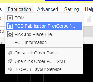 Create the circuit schematic and export PCB Gerber files.
Gerber files are a standard file format used in PCB fabrication that contains information about the PCB’s copper layers, solder mask, legend, and drill and route data. Make sure to unpack the files for the next step. This step has important implications for the rest of the step. I recommend the following design rules to start: 2mm traces (1.5mm is ok, but bigger is better here) .49mm clearance (tends to work well with 2mm traces on through hole components, avoiding rounding errors and still giving .5mm clearance, basically, since the traces are 2mm). 1mm vias and holes, so the trace has about .5mm on either side of the via so it has room once the eyelet is punched through.
If clearance problems arise, or smaller tools are available, the minimum design settings ought to be adjusted here instead of attempting it later in CAM.
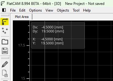
1: Prepare the Geometries and Save CNC Instructions with FlatCAM
FlatCAM is a free and open-source application that can be used to prepare the geometries and generate the CNC instructions for milling the PCB. It can be used to load the Gerber files and generate the CNC instructions for the milling machine to execute.
1.1: Open the Gerber files
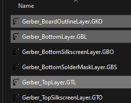
Opening the gerber files in FlatCAM will immediately shows the PCB layout and the traces and pads that need to be isolated
1.2: Open the Excellon Drill files
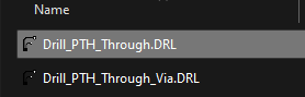
These are the drill files that contain the locations of the holes that need to be drilled in the PCB. Open these files in FlatCAM to see the locations of the holes.
Likely, only one file file that contains all drill locations needs loading.
The other file is for vias, which seem to be contained within the overall PTH file.
1.3: Use the 2 Sided PCB tool


Using the 2 Sided PCB tool, the bottom side of the board must be mirrored, and guide holes setup that will assist with aligning the PCB after flipping it on the X or Y axis (this is a preference thing) It is essential to perform this step first since the bottom layer isolation needs to be done against the mirrored layer, so it aligns with the top. Mirror the bottom layer as opposed to the top, so that the through holes align properly without any extra mirroring steps.
It’s a good idea to reserve the origin 0,0 for probing the tool height electrically, and so alignment holes should be placed elsewhere. Also, don’t put any holes in the area where the PCB will be cut out, because these will likely show up in the final product. A reasonable place for alignment holes is (-1,-1),(2,-1) mirrored on the X axis, so FlatCAM will generate 4 holes.
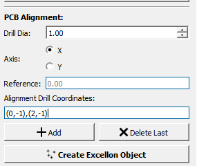
Make sure that the reference setting is using the gerber file for the outline layer as opposed to detecting geometry. This is the easiest way to ensure proper mirroring and alignment.
1.4: Isolate the Traces and Pads
Use the Isolation tool to isolate the traces and pads for the top and bottom layers. I use a 0.5mm tool for this. I have found the best settings are:
- Passes: 3
- Overlap: 50%
- Cut Z: -0.11mm
- MultiDepth: Yes
- DPP (Depth per pass): 0.03mm
- Feedrate x-y: 200mm/s
- Feedrate Z: 60mm/s
- Spindle Speed: 800rpm
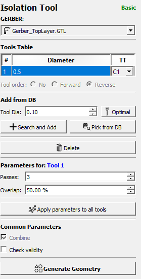
Click Generate Geometry to see the isolation cuts. The tool will generate the geometry for the isolation cuts, and the CNC instructions can be saved as G-Code.
When running the CNC job in candle, there is a slider to tweak the feed rates and spindle speed. These settings are semi conservative with that in mind, since the slider goes to 200%.
Feed rate and DPP can be tweaked in an attempt to speed up the process. Higher DPP means slower feedrate, and vice versa.
Step 1.5: Use the tool to generate cutout geometry

Use the Cutout tool to generate the geometry for cutting out the PCB from the blank copper clad board. Select a bit that is large enough to cut through the board, but small enough to fit into the tightest corners of the PCB. I use a 2.4mm bit for this. Settings will vary depending on the thickness of the board, but in general the multipass method works well here too.
Avoid excessive speed or cut depth in a single pass. These bits cut better shallow.
Step 2: Generate the G-Code
For each of the operations above, geometry or Excellon files were generated or loaded. These files can be used to generate the G-Code that the CNC machine will execute to mill the PCB. Double click on all the objects in the project to generate the G-Code for each of the operations. Save the G-Code same directory as the project file.
Some of the parameters mentioned in step 1+ are actually set in the G-Code generation step, so it is important to double check these settings.
3: Mill the PCB
Once all the G-Code is generated, the CNC machine can be set up to mill the PCB. The following steps outline the process I follow to mill the PCB.
3.1: Set up the CNC machine
Set up the CNC machine with the hole drilling bit at 1mm. Add the copper clad board to the CNC machine and secure it in place. Make sure the copper clad board is square to the CNC machine and secure.
3.2: Set the origin
Select a point to designate the origin. Leave enough margin around the tool to avoid collisions with the clamps.
Ensure the working coordinates are x=0 and y=0 (click the “set zero” button in candle)
Using a probe, find the tool height at the origin. This will set the Z=0.
3.3: Generate a height map
No PCB is perfectly flat. Mounting hardware affects the overall flatness of the board, and once it is moved, the height map is no longer valid. A height map can be generated using the probe, and the CNC machine can be programmed to adjust the Z height as it moves around the board to account for the height differences. Using the latest version of Candle, this is a built in feature. It is a necessity for a good isolation cut. Without using a height map, the isolation cut will be inconsistent, and the traces will not be fully isolated, and copper will be left behind, causing short circuits.
Load the CNC code for the cutout layer, and use that to auto set the height map box to ensure the entire board is within the height map.
Click the probe button, and the CNC machine will probe the entire board and generate a height map. File->Save this height map. Now click the edit button again, and exit out of that mode.
Now load the CNC code for the alignment holes. This will clear the height map, so open the file saved in the previous step, and be sure to check “use height map”.
Click the send button, and the CNC machine will use the height map to adjust the Z height as it moves around the board to account for the height differences while it drills the alignment holes.
3.4: Repeat the process for the through hole CNC code and top layer isolation CNC code.
The height map will clear each time and will need reloading for each operation.
3.5: Flip the board and align with the alignment holes.
This step is a bit manual, but it is important to ensure that the top and bottom layers are aligned properly. The alignment holes will help with this. Optionally, one might use pegs or a jig to ensure the board is aligned properly.
The method I use is to flip the board, and get the drill bit as close to the first alignment hole as possible. It helps to load the Excellon file for the alignment holes in a text editor, because the alignment holes are in specific locations, and the CNC machine can be programmed to move to those locations easily by copying the g-code from the text editor and pasting it into the command line in Candle.
Continue the process of moving the CNC machine to each of the alignment holes coordinates, and then lowering the drill bit into the hole. Once the drill bit is in the hole, the CNC machine can be programmed to move to the next hole, and the process can be repeated until all the holes are perfectly aligned.
Clamp down the board, and re-measure the alignment holes to make sure clamping the board down didn’t move it.
3.6: Generate a height map for the bottom layer
Repeat the process of generating a height map for the bottom layer. This will ensure that the bottom layer isolation cut is consistent and that the traces are fully isolated. Note that there are 1mm holes all over the board, so the bit used to probe will need to be large enough to not fit into the holes. I actually turn my bit upside down or use a non conductive probe. Save the height map overtop the original, since the original is no longer needed or valid.
3.7: Load the 0.5mm isolation tool and find the Z height
Load the 0.5mm isolation tool, and use the probe to find the Z height at the origin. This will set the Z=0 for the bottom layer isolation cut.
3.8: Run the bottom layer isolation CNC code
Load the bottom layer CNC code, and reload the height map. Make sure to check “use height map” Click the send button, and the CNC machine will use the height map to adjust the Z height as it moves around the board to account for the height differences while it isolates the bottom layer.
3.9: Cut out the PCB
Load the cutout CNC code, and reload the height map. Make sure to check “use height map” again. Load the cutout bit into the CNC machine and use the probe to find the Z height at the origin. This will set the Z=0 for the cutout.
Now the PCB is ready to be cut out. Click the send button, and the CNC machine will use the height map to adjust the Z height as it moves around the board to account for the height differences while it cuts out the PCB.
To be continued…